Cranes on Ships: Introduction to Crane Integration
In the marine world, we see cranes daily; they are very useful pieces of equipment. Despite their common appearance, we need to remember their potential for disaster. Cranes on ships generate new, subtle risks for lifting operations. Unless you know what to look for, the risks can go undetected. This article reviews the major dangers of cranes on ships.
1.0 Introduction
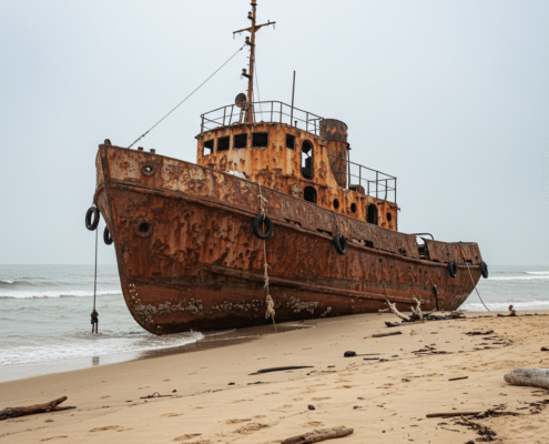
When big cranes fail on big ships, we get big disasters. (Figure 1‑1) These failures are rare, but they do happen. Frequently, these failures originate from a lack of knowledge. Understandable, since cranes create very subtle risks, difficult to recognize unless you know what to look for. Today, I review the major risks generated when we put a crane on a ship.
Figure 1‑1: Example of Crane Failure [1]
2.0 What is a Crane?
The first danger: you may not realize that you have a crane on your ship. From a pure physics perspective, a crane is any device that combines two qualities: moving a heavy weight, and lifting that weight vertically. This includes:
Boom cranes
Folding cranes
Drill derricks
Excavators
Some commercial fishing gear
Underway replenishment equipment
Construction cranes on barges
Often, dangers with cranes come from civil construction crews that start expanding into marine work. This starts with good intentions and best practice. Barges look very stable; you would never question its safety for a crane operation because the barge feels rock solid. But the stability requirements for a crane go far above the typical barge mission. Then someone might argue for a plan to mitigate any unknown risks:
Only lift the load a small height.
Keep the crane oriented over the bow of the barge.
Use slow movements to prevent any swinging.
This is the right plan, but it overlooks four new risks:
Stability (will the ship capsize)
Structure (will the crane punch through the deck)
Marine Systems (how do we get power to the crane)
Dynamic Forces (in the open ocean, ships and cranes move around)
2.1 Side Note for Civil Construction
If you work in the United States and perform construction work for the Army Corp of Engineers (COE), check with a naval architect before doing any lifting work on water (including excavators on a barge). The COE takes floating lifting very seriously, and they require an extensive engineering analysis to prove safety. Getting the proper engineering work requires a few weeks to a month per crane. This is not a minor piece of paperwork.
3.0 Stability
Imagine placing a crane with a 1000 LT capacity onto a ship, only discover that your crane is now restricted to half its original capacity! Behold the effects of ship stability; our capacity depends on the properties of both the crane and the vessel. The stability of your platform limits cranes in three ways:
Max vertical height
Max heeling moment
Max incline angle
Vertical height is the hidden devil. All vessels (ships and barges) have a maximum limit for the height of their deck cargo. That limit may be only 3 m. above the deck, or 30 m. But you will never know from just looking at the ship. The limit on vertical height depends on several complicated interactions, and you need a naval architect to tease out the hidden properties and report that limit.
But how to keep the crane under that vertical limit? Naturally, focus on your hook load. The thing you are lifting. If the vertical limit is 5 m., don’t lift the load more than 5 m. above the deck, right? WRONG! Your crane sits on a ship that heels and reacts to shifting weights, which means different rules for vertical limits.
We measure the limit on load height to the tip of the crane boom. As the ship heels over, the suspended load swings from the tip of the crane boom and shifts further in the direction of heel (point s in Figure 3‑1). Thanks to the physics of stability, the vessel behaves as if your suspended load sits at the tip of your crane boom, regardless of the actual hook height. Think about a crane with a long boom and its boom tip 70 m. above deck. The instant your load leaves the deck, the vessel thinks you just placed it 70 m. in the air! This is how cranes on vessels escalate into high-risk lifts.
This vertical limit also changes with the heeling moment generated by your crane. As the crane moves a load further over the vessel side, it increases the heeling moment. Each vessel has their own max limit for heeling moment, but that limit depends on the vertical height of your load. Think of it like this: stability is a balance between the heeling moment of your crane and the righting moment of the ship. The righting moment depends on the height of your boom tip. Higher booms reduce righting moment. Heeling moment depends on the horizontal position of your hook load. This feedback loop quickly limits the safe hook load, all due to stability.
To capture all this complexity, we create a custom lifting chart that details allowable load limits for every position of the crane boom. These lifting charts marry a specific combination of vessel and crane. Change one piece of that configuration, and the entire lifting chart needs to be adjusted.
The load chart also considers crane limits on incline angles. Even if the vessel stability accommodates large heel angles, the crane may not like it. Most land cranes operate on relatively level ground. This assumption gets built into their structural design. Hence why crane manuals specify a limit on ground incline of 5 deg, for example. If the crane starts with more than a 5 deg incline, the boom may buckle and break. (Figure 3‑3) Easy to avoid on the nice solid land, just measure the angle before starting any lift.
But on a vessel, the ground starts level and inclines after you pickup the load. The solution to this problem: get a crane designed for larger incline angles, or make sure the ship never heels past your incline limit. This requires computer simulations to check all the complicating factors and guarantee heel angles (and trim angles) remain under the limits. That is the value of a naval architect. We check for failure dozens of times on the computer to ensure you never fail in real life.
Figure 3‑3: Barge Heel Created Crane Failure [1]
4.0 Structure
All the stability in the world doesn’t matter if the crane breaks through the deck of the ship. Ships structures were generally designed for soft distributed loads, like the water pressure of the ocean. But cranes create large, concentrated loads, like punching a hydraulic ram through sheet metal. Bad things happen, unless we reinforce the ship.
Now the naval architect switches over to structural design. Take the example of a crawler crane on a barge. We analyze each piece of structure under the deck of the barge and ensure they can safely transfer the forces from the crane, down through the barge’s hull. But don’t forget that the crawler crane moves, which changes the high stress locations. One analysis turns into dozens. This is where experience shows an advantage. Based on past knowledge, the engineer considers all the different crane positions and reduces them down to only 2 or 3 critical cases. Far less analysis, with a smaller engineering budget.
Of course, bigger engineering leads to larger projects. With larger cranes, the structure becomes so critical that we permanently mount the crane to the ship and design a custom foundation that distributes the stresses into the ship hull. The ship itself is now construction equipment, but cranes still need robust designs. Even the foundation plans for emergency scenarios. We typically build the crane foundation stronger than the crane itself. If disaster strikes, the crane may fail, but that failure doesn’t cascade through the ship’s hull. Figure 4‑1 shows the aftermath of a crane failure. The crane boom failed, but the foundation held strong. The safety systems worked.
Figure 4‑1: Crane Foundation Design [4] (Crane Structure Failure)
This failure reveals the complexity of structural design for cranes. Our designs encompass multiple scenarios, including several emergency scenarios. The complexity of foundation design requires its own article to properly explain. For today, I will just emphasize that everyone on the team needs to communicate their design scenarios and apply them to every part of the crane structure. Ironically, the damage on that offshore vessel apparently started with the failure of a single pin on the crane hook. [5] Even the smallest component harbors the potential to ruin the entire system.
Figure 4‑2: Failure of Crane Hook During Load Test [6]
5.0 Marine Systems
Cranes all need power for their mechanical systems. Typically, the crane vendor controls all the internal machinery of the crane, and the marine engineers provide a power connection. But this requires more effort than plugging in an extension cord.
With permanent cranes, the vessel provides power, normally through hydraulic lines or electric cables traveling up the center of the crane pedestal. This creates a practical problem: the crane rotates. Most cranes are free to slew (horizontal rotation) without restriction. How to physically connect power lines to a rotating structure? For electrical supply, the common solution is a slip ring assembly, positioned directly on centerline of the crane. (Figure 5‑1) Hydraulic supplies use a similar approach with rotating joints.
Some cranes go for a simpler solution: keep the power completely self-contained, in the case of a crawler crane on a barge. Crawler cranes use their own engines and fuel tanks. It all depends on the crane. They each have their own approach and unique requirements.
6.0 Conclusion
Interfacing cranes with vessels plays out differently every time. It takes a creative engineer to generate solutions for each new problem. Despite these unique solutions, the problems all fall into the same risk categories: stability of the ship, design limits of the crane, structure limits of the ship, and interfacing marine systems. The biggest risk is complacency. In the marine world, we see cranes daily; they are very useful pieces of equipment. Despite their common appearance, we need to remember their potential for disaster, stay diligent in identifying those risks, and create useful guidance to keep people safe.
7.0 References
[1]
Onderzoeksraad voor Veiligheid, “Lifting Accident Alphen aan den Rijn,” YouTube, 29 Jun 2016. . Available: https://youtu.be/LJevke4_i5Y. .
[2]
K. J. Rawson and E. C. Tupper, Basic Ship Theory, 5th Ed. Volume 1, Woburn, MA, USA: Butterworth-Heinemann, 2001.
[3]
Weeks Marine, Inc., “Floating Crane Barge – Info Sheet (Weeks 554),” Weeks Marine, 17 Oct 2018. . Available: https://www.weeksmarine.com/docs/default-source/default-document-library/weeks-554-crane-barge_info-sheets_-20181017.pdf?sfvrsn=dcb798df_0. .
[4]
YouTube Creator: AtTheGarage, “Accident with Offshore Liebherr Crane int he Port of Rostock,” YouTube, 2 May 2020. . Available: https://youtu.be/6BJTLRfWocM. .
[5]
T. Pieffers, “Hook Designer Ropeblock “Appalled” by Orion Accident,” Project Cargo Journal, 07 May 2020. . Available: https://www.projectcargojournal.com/equipment/2020/05/07/hook-designer-ropeblock-appalled-by-orion-accident/?gdpr=deny. .
[6]
M. Adams, “Failure of Crane Hook During Load Test,” YouTube, 7 Jan 2021. . Available: https://youtu.be/o1s79Uk10TA. .
[7]
Moflon, “Everything you Need to Know About Slip Ring Assembly,” Moflon, 11 Oct 2018. . Available: https://www.moflon.com/showen153.html. .
[8]
B. v. Ubisch, “Installation Vessel Orion was Whiplash Proof, but its Crane Was Not,” SWZ Maritime, 17 Sep 2020. . Available: https://www.swzmaritime.nl/news/2020/09/17/installation-vessel-orion-was-whiplash-proof-but-its-crane-was-not/?gdpr=accept. .
https://dmsonline.us/wp-content/uploads/2025/08/Clickbait.jpg7201280Nicholas Barczak/wp-content/uploads/2025/06/DMS-logo.svgNicholas Barczak2025-11-11 07:00:002026-06-01 10:09:18How to Buy a Towing Tank: Purchase and Design Guide
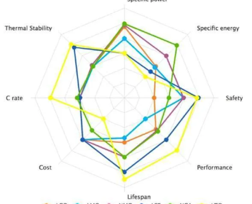
https://dmsonline.us/wp-content/uploads/2022/09/Lithium-Chemistries-Spider-Chart.webp513589Nate Riggins/wp-content/uploads/2025/06/DMS-logo.svgNate Riggins2023-03-06 08:00:002025-08-15 10:30:12Batteries for Electric Propulsion
We may request cookies to be set on your device. We use cookies to let us know when you visit our websites, how you interact with us, to enrich your user experience, and to customize your relationship with our website.
Click on the different category headings to find out more. You can also change some of your preferences. Note that blocking some types of cookies may impact your experience on our websites and the services we are able to offer.
Essential Website Cookies
These cookies are strictly necessary to provide you with services available through our website and to use some of its features.
Because these cookies are strictly necessary to deliver the website, refusing them will have impact how our site functions. You always can block or delete cookies by changing your browser settings and force blocking all cookies on this website. But this will always prompt you to accept/refuse cookies when revisiting our site.
We fully respect if you want to refuse cookies but to avoid asking you again and again kindly allow us to store a cookie for that. You are free to opt out any time or opt in for other cookies to get a better experience. If you refuse cookies we will remove all set cookies in our domain.
We provide you with a list of stored cookies on your computer in our domain so you can check what we stored. Due to security reasons we are not able to show or modify cookies from other domains. You can check these in your browser security settings.
Other external services
We also use different external services like Google Webfonts, Google Maps, and external Video providers. Since these providers may collect personal data like your IP address we allow you to block them here. Please be aware that this might heavily reduce the functionality and appearance of our site. Changes will take effect once you reload the page.