How to Design a Ship
How to design a ship? How to go from a blank sheet of paper to a sensible design for a ship, when you have nothing to start with? So here are my secrets revealed.
How to design a ship? How to go from a blank sheet of paper to a sensible design for a ship, when you have nothing to start with? So here are my secrets revealed.
How to design a ship? Not an easy question. A student prompted this with a question, and the only answer I had required a few semesters of college courses. They wanted to know how to create a general arrangement drawing for the ship. But to create a general arrangement, you need to first design all the major parts of the ship. The real question that student asked: how to go from a blank sheet of paper to a sensible design for a ship, when you have nothing to start with?
So here are my secrets revealed. How to design a ship.
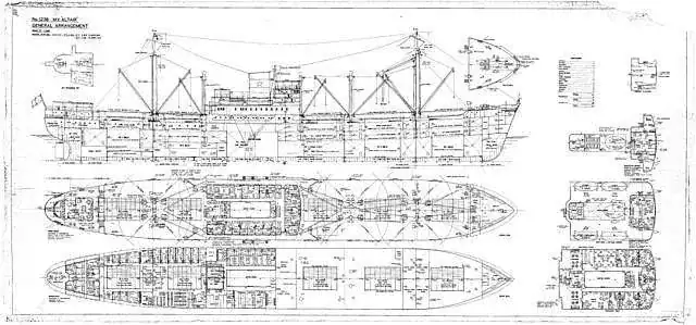
The general arrangement drawing is the equivalent to the floor plan of a house. (Figure 2‑1) It doesn’t show any specific construction details. The general arrangement orients you to the ship, shows the major bulkheads, the general shape of the hull, floor layout on each deck. This is the starting drawing for any ship.
It’s also the hardest drawing to create when starting from scratch. Designers don’t arrive with a perfectly formed ship in their mind. Ship design begins as a murky image of a nebulous blob, which hopefully floats. It takes several rounds of trials and refinements to complete the initial process. The general arrangement drawing lies at the end of these refinements. When asking how to create a general arrangement, the real question is: how to design a ship from scratch?
Creation starts with boredom. Everyone wants to leap into sketching out the hull shape and locating rooms. I give into that temptation too, starting with a few hand sketches. But hand sketches will not become the governing factor in your design. The biggest concern will always be weight.
A ship needs sufficient buoyancy to support all its weight. This controls the basic size of the ship. Which means we can’t even get a hull size until we know how much weight to support. Of course, one of the biggest weight components is the hull itself. We need to design the ship so we can find the weight . . . so we can size the ship to design it. That’s a frustrating loop.
How to break the loop? Take a guess. No, seriously. The first weight estimate involves educated guesses about the ship weight, usually based on some other ship of similar size. Every naval architect has their own secret method. We use fancy words like parametrics and heuristic equations. All variations of educated guesses, some better than others.
On top of the ship weight, was also require the center of gravity, especially the longitudinal center (LCG). Most ships have the center of gravity fairly close to the middle of the ship. But imagine that you create a massive deckhouse on the stern, six decks tall. That’s a lot of weight to put on the back. How much did that shift the overall center of gravity? With a lot of weight back aft, we also need to shift the buoyancy aft by making the hull wider in the stern. Weight and LCG dictate the requirements for the hull shape.
Weight estimates are tedium: just plain boring. The only way is to go through every major item on the ship and guess at each component: weight of fuel, weight of cargo, weight of ship structure, weight of major equipment, etc. Very boring. And nerve wracking, since every entry is a guess in the first iteration. You come out of the weight estimate either doubting every single entry . . . or you develop a healthy sense of bravado to comfort yourself.
In addition to weight, we also worry about volume: the space required. Imagine that I have two ships. One carries a tonne of steel, and the other carries a tonne of feathers. They both have the same weight. But the feather ship needs a lot more space for its cargo. We need to estimate the volume required for everything. This includes all the usual suspects:
But it also includes some hard to estimate components. For example, how much space do people require? Think about a normal house. Lots of space not currently occupied by a human. Or what about major equipment? How much space for the main engine, and all its supporting machinery? How big to make the engine room? Those get tricky.
Again, we turn to educated guesses for every component and add up the total.
With the weight and volume, we begin designing the hull shape. The weight controls the underwater volume of the hull. But a normal hull includes a large portion above the water. The volume requirements control the total volume of the hull (underwater and above water). Largest hull requirements win.
That only speaks to the size of the hull. What about the shape? Naval architects use several coefficients to give them hints about the appropriate shape. This becomes a contest between competing needs on the ship. To minimize fuel consumption, we want the hull cross section to form a perfect circle, and narrow as a needle lengthwise. But any ship with that shape will flip over the minute it touches water.
Stability competes to control the hull shape. There are two general cross sections that make for good stability. Either go wide and shallow or go deep and narrow. Of course, those two shapes are also the worst for powering. The solution: compromise.
We start with a stable hull shape. And then we compromise, trending towards that narrow needle shape. The trick lies with learning how close you can get to the needle and still maintain enough stability. Again, this is a process of guess and check. Take a guess at the hull shape, run it through the design, and discover if the gods favored you with enough stability. Realize you were wrong and modify the design.
I talked about the process for the hull shape, but how do we actually draw it? Enter the lines plan. A lines plan drawing shows the 3D shape of the hull. Just the shape, none of the construction details. This documents the size of the ship, the space available on each deck, and determines the ship stability. When creating a lines plan, we favor smooth shapes, with gradual curves.
The trick of a lines plan lies in creating smooth curves in all three dimensions. Many people use generic drafting programs for the lines plan, some even working in 2D. At a minimum, any package should work on the full 3D hull shape at once. Otherwise, you miss bumps in the hull shape and other irregularities. Personally, I like to use dedicated software specific for creating ship lines plans. (Figure 5‑1) This allows easier editing of the shape and includes some extra tools to detect problem spots. Any irregular curve or bump adds to the hull resistance and increases fuel consumption. When we talk about a smooth hull shape, our real focus is the ship’s fuel consumption.

After drawing the lines plan, we need to check the hull shape. Examine basic hydrostatics and stability. Full hydrostatics can take several days or weeks to check. At this stage, we focus on a few big points. First, check the buoyancy. Do we have enough to support the estimated weight?
Second, look at the longitudinal center of buoyancy (LCB). Ensure this matches fairly close to the longitudinal center of gravity (LCG). Otherwise, your ship tries to trim forward and do a reenactment of the titanic pitching down. In the final design, the LCG and LCB need to be in the same location for a level trim on the ship.
Third, we perform some basic checks on stability. Usually focusing on the metacentric height (GMt). Without explaining a college course on stability, just know that a GMt of zero or less means the ship capsized. Bad. We want a positive GMt, with some fair amount of margin. A GMt of 2.0 m can be a good starting point, if you have no other stability criteria for guidance. But the exact requirements change radically with the ship type and service.
With the hull shape defined, we now have the envelope for our ship. Time to finally create the general arrangement drawing and fit everything inside that envelope. Start with the major structures first, and then work down to the minor pieces. The watertight bulkheads form some of the most critical boundaries. We carefully space these bulkheads to limit the effects of flooding. Few people realize that the bulkhead locations are a safety feature inherent to the ship.
Beyond that, tanks, cargo holds, and the engine room define the other major structures in the hull. We need to carefully coordinate between the different decks. Good structural design insists that major bulkheads align with each other from one deck to the next. For example, the front of the deckhouse needs to land on a bulkhead in the hull. This ensures robust support for the deckhouse. The general arrangement drawing becomes a jigsaw puzzle, maintaining alignment between all these rooms and structures. Good luck. You won’t get it right the first time.
The general arrangement demands a LOT of trial and error. For faster development, I like to start with hand sketches. My preferred technique:
Once we arrive at a satisfactory arrangement, we redraw the entire sketch in our CAD software to finally generate the formal general arrangement drawing. Congratulations, you now have a ship. Maybe.

Did you think you were done? After the first round, you likely discover that several items do not match. The hull was just a little too small, with not quite enough buoyancy. Maybe we forgot a space for the emergency generator. Is the galley in a broom closet? Remember: this whole process started with educated guesses. And guesses tend to be wrong. Use your current design as a starting point and repeat the entire process. It normally takes 2-4 rounds of iterations to arrive at a feasible ship design.
Starting with a brand new ship concept requires a lot of trial and error. Not easy. This is why most ship designs copy each other or use heuristic formulas for their starting point. But every heuristic formula uses data from past ships. These formulas only tell you how to copy previous ship designs.
DMS takes an alternative approach. We developed an extensive design application (NeoShip), based on MS Excel, which contains every aspect of a ship design. (Figure 9‑1) It avoids all heuristic formulas, favoring simplified physics that still respect the dependencies between various ship design aspects. The entire concept design process, contained in one application. This makes it very easy to try several different combinations of ship parameters and see instant results.
Any ship design allows hundreds of possible combinations for the major parameters. How to find the best option? NeoShip employs a custom evolutionary optimizer. The optimizer works tirelessly through the night, checking hundreds of variations in design parameters to select the best options. This approach allows DMS unparalleled flexibility with exploring all the options of a new vessel design. Key advantages are:
NeoShip generates a massive set of vessel outputs, far more than your normal concept design. This provides an extremely robust starting point for the next design iteration. NeoShip even considers ship economics, focusing on profit for the ship right from the initial synthesis.
One great example of NeoShip was a concept I developed for a small container ship. With the evolutionary optimizer, I discovered a huge advantage by going from six to seven rows of containers. All my classic training biased me to reject this option initially. I thought it would make the hull too wide, generate too much resistance and increase fuel consumption. All those things happened, but a whole extra row of containers generated far more revenue. It justified the increased operating costs. Humans don’t always see these options; our biases unconsciously direct a concept design. But NeoShip has no bias. In the time it took me to complete one concept design, it tested hundreds of possibilities, finding that unique and elegant solution. That was the power of automated design. The advantage of NeoShip.

Genesis of a new ship design is never easy. Fraught with uncertainty, it begins with guesswork, and the guesses are often wrong. Programs like NeoShip improve this process, allowing far more iterations and design exploration. But even without NeoShip, the key to a successful design lies in tedium. Focus on the weight estimate and volume estimates. These can make or break a design. After that, repetition. Guess, check, and repeat. Finally, at the end, we arrive at a general arrangement drawing. Like so many achievements of skill, the general arrangement shows the end result, but not the diligent work behind it.
| [1] | Museum of Hartlepool, “MV Altair – General Arrangement Plan,” Wikimedia Commons, 18 Feb 2010. . Available: https://commons.wikimedia.org/wiki/File:MV_Altair_-_General_Arrangement_Plan_(6124203966).jpg. . |
 https://dmsonline.us/wp-content/uploads/2025/08/ShipDrydock1-scaled.jpg
1920
2560
Nicholas Barczak
/wp-content/uploads/2025/06/DMS-logo.svg
Nicholas Barczak2025-10-21 07:00:002026-04-29 10:09:57Why You Want an Upgrade: Major Ship Refits
https://dmsonline.us/wp-content/uploads/2025/08/ShipDrydock1-scaled.jpg
1920
2560
Nicholas Barczak
/wp-content/uploads/2025/06/DMS-logo.svg
Nicholas Barczak2025-10-21 07:00:002026-04-29 10:09:57Why You Want an Upgrade: Major Ship Refits https://dmsonline.us/wp-content/uploads/2023/12/HabbakukCover-Small-1.jpg
489
500
Nate Riggins
/wp-content/uploads/2025/06/DMS-logo.svg
Nate Riggins2024-09-24 09:18:002026-04-29 10:09:59Project Habbakuk: A Ship from Ice!
https://dmsonline.us/wp-content/uploads/2023/12/HabbakukCover-Small-1.jpg
489
500
Nate Riggins
/wp-content/uploads/2025/06/DMS-logo.svg
Nate Riggins2024-09-24 09:18:002026-04-29 10:09:59Project Habbakuk: A Ship from Ice!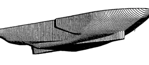 https://dmsonline.us/wp-content/uploads/2023/12/Icebreaker_SpoonBow.webp
217
598
Nate Riggins
/wp-content/uploads/2025/06/DMS-logo.svg
Nate Riggins2024-07-16 09:00:002026-04-29 10:09:59Strong as Ice: Icebreaker Structure
https://dmsonline.us/wp-content/uploads/2023/12/Icebreaker_SpoonBow.webp
217
598
Nate Riggins
/wp-content/uploads/2025/06/DMS-logo.svg
Nate Riggins2024-07-16 09:00:002026-04-29 10:09:59Strong as Ice: Icebreaker Structure https://dmsonline.us/wp-content/uploads/2023/12/USCGC_Healy_WAGB-20_north_of_Alaska-scaled-1.jpg
633
1200
Nate Riggins
/wp-content/uploads/2025/06/DMS-logo.svg
Nate Riggins2024-05-14 09:00:002026-04-29 10:10:00Surviving the Arctic: Polar Class Icebreakers
https://dmsonline.us/wp-content/uploads/2023/12/USCGC_Healy_WAGB-20_north_of_Alaska-scaled-1.jpg
633
1200
Nate Riggins
/wp-content/uploads/2025/06/DMS-logo.svg
Nate Riggins2024-05-14 09:00:002026-04-29 10:10:00Surviving the Arctic: Polar Class Icebreakers https://dmsonline.us/wp-content/uploads/2023/12/MackinawIce1-scaled-1.jpg
883
1200
Nate Riggins
/wp-content/uploads/2025/06/DMS-logo.svg
Nate Riggins2024-03-19 09:00:002026-04-29 10:10:00Ramming the Ice: Icebreaker Propulsion
https://dmsonline.us/wp-content/uploads/2023/12/MackinawIce1-scaled-1.jpg
883
1200
Nate Riggins
/wp-content/uploads/2025/06/DMS-logo.svg
Nate Riggins2024-03-19 09:00:002026-04-29 10:10:00Ramming the Ice: Icebreaker Propulsion https://dmsonline.us/wp-content/uploads/2023/12/MackinawIce2-scaled-1.jpg
1200
985
Nate Riggins
/wp-content/uploads/2025/06/DMS-logo.svg
Nate Riggins2024-01-16 09:00:002026-04-29 10:10:01Breaking the Ice: Icebreakers
https://dmsonline.us/wp-content/uploads/2023/12/MackinawIce2-scaled-1.jpg
1200
985
Nate Riggins
/wp-content/uploads/2025/06/DMS-logo.svg
Nate Riggins2024-01-16 09:00:002026-04-29 10:10:01Breaking the Ice: Icebreakers https://dmsonline.us/wp-content/uploads/2022/02/ClickBait1_1.84.1.jpg
1080
1920
Nate Riggins
/wp-content/uploads/2025/06/DMS-logo.svg
Nate Riggins2022-02-21 06:00:002025-08-15 13:17:02Stability Letters Explained
https://dmsonline.us/wp-content/uploads/2022/02/ClickBait1_1.84.1.jpg
1080
1920
Nate Riggins
/wp-content/uploads/2025/06/DMS-logo.svg
Nate Riggins2022-02-21 06:00:002025-08-15 13:17:02Stability Letters Explained https://dmsonline.us/wp-content/uploads/2022/01/Subsea-Knuckleboom-Cranes-Full.jpg
1080
1920
Nate Riggins
/wp-content/uploads/2025/06/DMS-logo.svg
Nate Riggins2022-01-21 12:06:422025-08-15 13:27:16Three Neat Tricks with Marine Cranes
https://dmsonline.us/wp-content/uploads/2022/01/Subsea-Knuckleboom-Cranes-Full.jpg
1080
1920
Nate Riggins
/wp-content/uploads/2025/06/DMS-logo.svg
Nate Riggins2022-01-21 12:06:422025-08-15 13:27:16Three Neat Tricks with Marine Cranes https://dmsonline.us/wp-content/uploads/2021/01/Seawise_University_wreck.jpg
1059
1412
Nate Riggins
/wp-content/uploads/2025/06/DMS-logo.svg
Nate Riggins2021-01-18 07:00:002026-04-29 10:10:02Free Surface Moment
https://dmsonline.us/wp-content/uploads/2021/01/Seawise_University_wreck.jpg
1059
1412
Nate Riggins
/wp-content/uploads/2025/06/DMS-logo.svg
Nate Riggins2021-01-18 07:00:002026-04-29 10:10:02Free Surface Moment