Mesh deformation is incredibly frustrating, complicated, unstable . . . and unavoidable if you want to incorporate body motions into computational fluid dynamics. (CFD) In some simulations, we need to move the actual body. For example, dropping a payload from under the wing of an airplane. The payload physically separates from the wing, while still experiencing fluid forces of airflow. Modeling these scenarios requires mesh deformation, changing the mesh on the fly, while still using that mesh to solve transport equations. Piece of cake, right? Let’s discuss some practical tips for modeling mesh deformation.
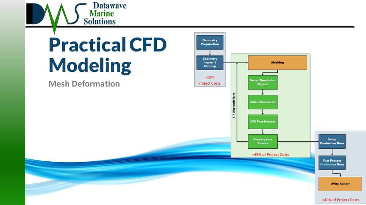
Mesh deformation greatly destabilizes your simulation. Expect increased residuals and large problems with simulation convergence. Plan ample time in your project for debugging, more debugging, and still more debugging. To combat the instability of mesh deformation, first craft your simulation without mesh deformation. Create a rock-solid stable setup, with excellent convergence and no problems at all. That forms the starting point to add in mesh deformation.
The problems with simulation stability arise from the changes in cell quality. Mesh deformation cannot automatically preserve the quality of the cells in the mesh. Cell quality deteriorates, and simulation stability suffers as a result. But not all cell changes pose equal trouble. Pure changes in volume remain relatively harmless. Changes in aspect ratio are safe in moderation. They lead to trouble when the aspect ratio starts to double from its original value. But the greatest villain is cell skew, usually generated by rotational mesh deformation. The key to protecting cell quality is picking the method of cell deformation. CFD engineers attempt to format the mesh and the motion so that most cells deform in the safer modes.
The CFD engineer must form a new level of meshing strategy. You must form the mesh at the beginning of the simulation to ensure a good quality mesh will result at end of the mesh deformation process. For example, if the mesh needs to stretch linearly, you may form an extruded mesh with the cells clustered near one end. As the mesh stretches, the concentrated cells stretch out, matching the aspect ratio on the rest of the mesh. The CFD engineer plans to achieve a mesh at the final shape, not the initial state.
Of course, the best strategy for mesh deformation is to minimize the distortion to the individual cells. We achieve this with large cells. Excessively large cells. The large volume permits large physical movement with minimal deformation to each individual cell. Sadly, large cell size contradicts the mesh resolution requirements to accurately resolve the transport equations near the body. Accurate resolution needs small cell sizes. Meeting both demands ends with two regions to the mesh. CFD engineers frequently designate an inner domain, with fine resolution mesh for the transport equations, and an outer domain used primarily to accommodate deformation and physical movement. As a result, the domain gets even larger for mesh deformation simulations.
When meshing for linear motion, like a piston compressing in a combustion cylinder, the main concern is elongated cell aspect ratio. To guard against this, CFD engineers typically employ extruded meshes. Bias the mesh in one direction, adding extra cells to accommodate the eventual mesh stretching. When the mesh stretches, these compressed cells stretch out to a normal aspect ratio, preserving the mesh quality.
With rotational motion, like a ship pitching in waves, you need to minimize cell skew. Try to maintain equal spacing between boundaries, this helps to ensure equal movement for each degree of rotation. The best strategy is to enclose your body inside an inner domain. Place all your major mesh refinements inside this inner domain. The inner domain should be cylindrical or spherically shaped. And then surround that with a much larger outer domain, also shaped as a cylinder or sphere. The cells in the outer domain are the only cells that actually deform, leaving the entire inner domain to move as a rigid body. This preserves cell quality near the body, giving you more freedom to mesh strictly for mesh deformation in the outer domain.
Mesh deformation requires patience and strategy. The simulation will likely crash on the first attempt, and the second attempt. The key to mesh deformation is to create extremely large cells, which creates another set of challenges that the CFD engineer works around. Rotational motion presents one of the largest challenges in mesh deformation, because it generates skew in the mesh cells. These are some of the many challenges that CFD engineers must balance when modeling for mesh deformation. Like any balancing act, the trick lies with patience and practice.
[1] | TCFD, “Axial Compressor CFD,” TCFD, 31 Dec 2018. . Available: https://www.cfdsupport.com/axial-compressor-cfd-simulation.html. . |
[2] | Atsushi Ueyama, “Progress of Time,” Cradle MSC Software Company, 31 Dec 2018. . Available: https://www.cradle-cfd.com/tec/column01/017.html. . |
[3] | YouTube Author: Holzmann CFD, “Holzmann CFD & OpenFOAM® – Dynamic Meshes in Multiphase Flows #2 (Topology Change, Ship Simulation),” YouTube, 10 Feb 2018. . Available: https://www.youtube.com/watch?v=B9KjnyDpsx0. . |