DON’T SWIM IN THE WATER! It may look like a swimming pool, but towing tanks have a different purpose. The deceptively simple act of dragging models down a pool of water propelled the science of ship design forward. From those experiments, we obtained extremely accurate and precise measurements to understand ship hydrodynamics. Today we discuss a central tool in the field of ship design, the towing tank.
Towing tanks are experimental facilities, used to test models of ships. William Froude argued for the first towing tank to predict ship resistance, back in the 1870. [1] (Figure 2 1) Back then, it was much easier to move the model than move the water. Even with modern technology, it still takes less power to move the model than to move the water, and the physics are more accurate. But, if we want to run a ship model down a trough of water, we need a very large trough.
Start by imagining a bathtub, and now scale that up to a giant basin of water several hundred meters long, deeper than a person, and wide as a car. Next dump a LOT of bromine into the water so that algae doesn’t grow. (safety warning: you do not want to swim in a towing tank.) Place that basin inside a climate controlled building. We need this because the experiments are so sensitive that even a 0.3° C change in water temperature affects the readings.
Next add the towing carriage, which is a large movable platform that stretches across the basin of water. (Figure 2 2) Think of it as a moving laboratory that runs on rails. We tow the ship models from the carriage, but the scientists also ride on the carriage. All the sensors to record the experiment feed to computers mounted on the carriage. And these are no ordinary sensors. Everything in a towing tank demands accuracy and precision. All focused on one goal: obtaining accurate measurements from the ship model as we tow it down a basin of water.
What do these measurements accomplish? Towing tanks provide a tool for solving hydrodynamics problems, via experimental methods. Simply put, it is very difficult to get accurate answers for hydrodynamic problems; they do not make for easy theories or easy mathematics. We have various approximations, but when you need accurate reliable numbers, nothing beats a towing tank. A single towing tank solves multiple types of hydrodynamics problems.
The most common test is the basic calm water resistance test. Ships use this to determine the power required at their design speed. The model gets towed down the tank at several specified speeds, and the scientists record the force on the model for each speed. Add in some special math to scale up the model result to full scale, and you have an accurate prediction of the resistance at each speed.
This test can be the most critical because ship construction contracts include major penalties if the ship does not make the predicted speed. Even losing 0.50 knots may incur penalties of $100,000 or more. So we need to ensure the predicted speed is undisputed. If lawyers get involved, we don’t want anyone questioning the science. The towing tank provides this undisputed prediction; it is the reference prediction that the shipyard will compare the final ship against. With thousands of dollars depending on the test results, everything in a towing tank needs to be beyond reproach.
A typical test program for calm water resistance would require testing the model at five speeds and two drafts. (5 speeds x 2 drafts = 10 runs total.) The first draft is the ship’s design draft, where it will eventually operate when fully loaded with cargo and fuel. But just out of the shipyard, on sea trials, most ship’s do not operate at their design draft. The shipyard doesn’t want to buy enough cargo and fuel to load the ship down to its design draft. Cargo and fuel are expensive! So the towing tank tests at a second draft: the draft planned for sea trials. If the ship matches predicted speeds for the sea trial draft, it should also match predicted speeds in the design condition.
If you want to test a new propeller design, you need flowing water. Propellers don’t require a towing tank exclusively; there are purpose built facilities just for testing propellers. But towing tanks can do double duty and test propellers as well. Instead of towing a model ship, we place a propeller on a strut underneath the carriage.
The strut has a motor with dynamometer installed to measure torque and RPM on the propeller. As the carriage moves down the tank, we spin the propeller at specific speeds to carefully simulate combinations of different propeller loads and ship speeds. This allows designers to test their new propeller design and get a clear picture of performance before we place it behind the ship.
The self-propulsion test forms the other half of the equation for powering prediction. (Figure 3‑3) The behavior of a propeller changes slightly behind the ship. At this level of accuracy, slight changes become important. The self propulsion test combines the ship model with the model propeller. The model propeller includes an electric motor and a dynamometer to measure torque and RPM. (We install these inside the ship model.)
The towing carriage tows the ship model down the towing tank at a fixed speed. During the test, the propeller increases speed. This may be a gradual increase, or a series of fixed speeds. (The procedure changes, depending on the tank.) At some point, the propeller produces sufficient thrust to eliminate all resistance force recorded by the towing carriage. Based on this crossover point, and the measurements from the other sensors, we calculate changes in propeller performance behind the ship. The technical terms are commonly known as the wake fraction, thrust deduction, and relative rotative efficiency.
Combine the calm water propulsion test, open water propeller test, and self propulsion test, and you have all the data you need for the definitive prediction of ship speed.
Even as the definitive standard for resistance prediction, not all towing tanks are equal. Size matters. This article doesn’t cover the mathematics of converting the model scale data from the tank into predictions for the full scale ship. But the theories are not perfect; minor inaccuracies exist.
The larger you make your model, the less you need to worry about those inaccuracies. Model scales of 1:20 are desirable, which means that the “model” for a standard Panamax container ship will be 14.7 m in length and weigh about 7.2 tonnes! Naval architects often joke about re-purposing the model afterwards and making it into a personal yacht.
Speaking of that massive model, who do you think will build it? They don’t sell these down at the RC hobby store. And these models must be manufactured to extremely tight margins, with their dimensions verified to less than a millimeter accuracy. (Figure 4 1) Most towing tanks come with their own model construction and storage facilities. A handy thing when you consider the logistics of how to move and preserve these massive models. Out of necessity, a towing tank evolves into a combination of industrial fabrication facility, precision scientific laboratory, and storage facility.
How much do you pay for all this accuracy and precision? A LOT! Because confidence is important. Imagine I asked you to measure you weight and your bathroom scale read 76 kg. Now imagine I put a gun to you head asked if the weight was exactly 76.0 kg. Not 76.1, not 75.0009. What if you stepped on the scale again? Would it still be exactly 76 kg? When we demand confidence in our numbers, we need both accuracy and precision, in the technical definition. That requires a higher standard of measurement. And confidence is difficult to achieve in practice.
The sensors used in these facilities do not come from Amazon.com. Each sensor gets precisely machined to the highest quality standards, calibrated and tested. They have the same provenance as a fine piece of art, carefully tracked and documented to maintain reliability. But that is just the start of what goes into a towing tank.
The measurement system of a towing tank is so delicate, it detects dozens of things completely unrelated to the experiment. Here are some examples:
Before a towing tank ever goes online, all of these factors need to be identified, explained, accounted, and possibly corrected. The tank constantly checks themselves and calibrates their equipment. They maintain reference tests and spend countless hours behind the scenes, all adding up to reliable test data with a margin of error around 1% or less.
The point is this: towing tanks are expensive because we demand confidence in our data, which is a difficult thing to reliably achieve.
The actual cost for tank testing varies, depending on a host of factors. This includes the economics of the country where you go to for your towing tank test. Towing tanks exist everywhere in the world, usually attached to major research universities. For a standard model construction and resistance test, I start my estimate around $20,000 USD, +/- 50%. About $10,000 USD to construct the ship model, and $10,000 to conduct the test. These are just rough numbers, intentional made vague to protect my sources. Each tank has their own contract, and your test will be customized to suit your needs. All of that affects the final price. The best approach is to start asking questions early and discuss options; don’t be afraid to obtain competitive quotes.
With the high price tag of the towing tank, many designers try to avoid the price and stick with empirical resistance estimates. Empirical methods work just fine for the initial design phase. But no shipyard will trust them with the risk of thousands of dollars in contract penalties. Empirical methods never check the specific ship; by definition, they are only an imperfect estimate. For ultimate confidence, you need the towing tank.
Many designers turn to computational fluid dynamics (CFD) as a cheaper alternative. CFD has many advantages. For the same scope of work, a CFD analysis would cost approximately $10,000 – $12,000 USD. The real advantage shines through if you want to test variations in hull shape.
In the towing tank, if you want to change the hull shape, you need to pay for constructing a new model. And then setup that model in the towing tank, which takes half a day to a whole day. Essentially, reset the entire experiment. But with CFD, things go easier in the virtual world of the computer. Just edit the geometry, and start a new simulation; total labor, less than two hours. For design optimization, the towing tank cannot compete against CFD.
But CFD will not replace the towing tank. First, there is the question of reliability. CFD has the capability to deliver results just as accurate as the towing tank, but towing tanks as an industry achieve this more consistently, thanks to standardization. Any towing tank worth talking to follows the standards of the International Towing Tank Conference (ITTC). The ITTC developed extensive standards for all the major tests, which ensured consistency among all the towing tanks. As a client, you don’t need to know anything about testing to ensure quality results. Just ask, “Do you conform to the ITTC standards?”
CFD does not have any equivalent to the ITTC. No uniformly recognized standard, despite attempts by multiple organizations. So you have no way to ensure reliable CFD operators. They may deliver CFD results with quality equal to the towing tank, or they may deliver garbage. Barring a uniform standard, the best you can ask for are validation studies from the CFD operator. This inconsistency is why towing tanks will remain the definitive standard for resistance and speed prediction
The towing tank is a fundamental tool of ship design. Where others may see a giant bathtub, I see confidence. The desire for confidence made manifest. Absolute confidence that the measurements yield definitive predictions for speed and powering. That is what a towing tank represents.
[1] | S. Slade, “History and Technology: Towing Tank Tests,” NavWeaps: Naval Weapons, Naval Technology and Naval Reunions, 19 December 1998. . Available: http://www.navweaps.com/index_tech/tech-010.php. . |
[2] | 
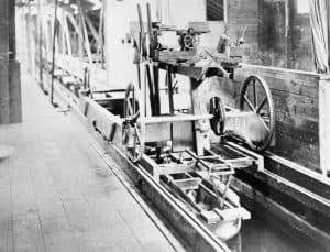
Wikipedia Contributor: Fae, “William Froude and the Admiralty’s First Naval Test Tank at Torquay, Devon, c 1872,” Wikimedia Commons, 28 Jan 2013. . Available: https://commons.wikimedia.org/wiki/File:William_Froude_and_the_Admiralty%27s_First_Naval_Test_Tank_at_Torquay,_Devon,_C_1872_HU82584.jpg. . |
[3] | 
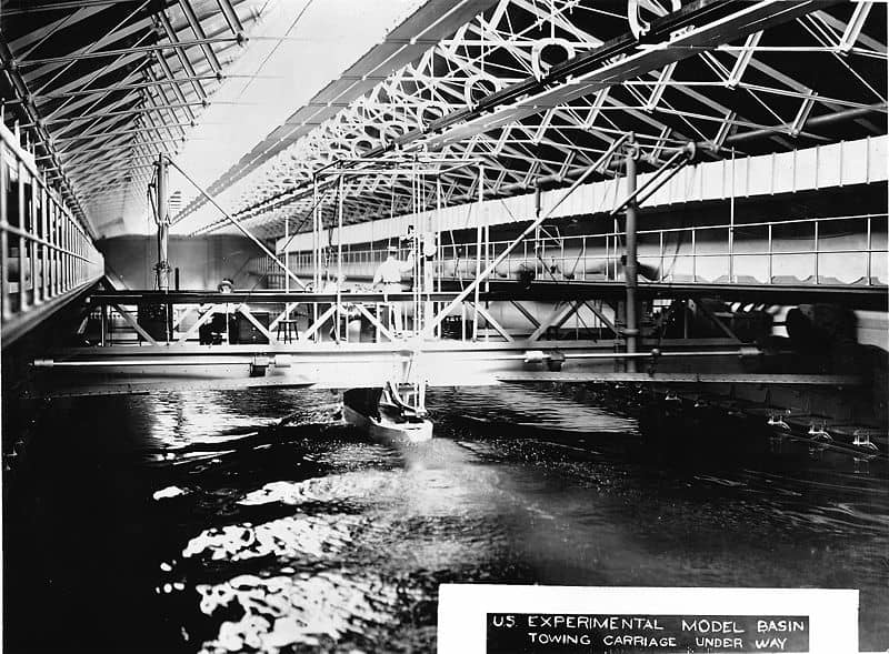
Wikimedia Authors, “Experimental Model Basin, Washington Navy Yard, Washington, DC – interior view, c. 1900. This was the first model basin (towing tank) for the United States Navy.,” Wikimedia Commons, 19 Aug 2007. . Available: https://en.wikipedia.org/wiki/File:US_Experimental_Model_Basin_-_interior_view,_c._1900.jpg. . |
[4] | 
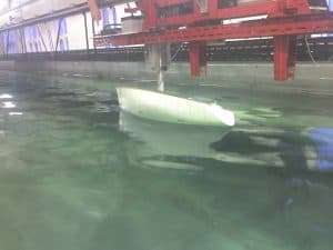
Wikipedia Author: FastilyClone, “NewcastleTowingTank.jpg,” Wikimedia Commons, 05 Mar 2016. . Available: https://commons.wikimedia.org/wiki/File:NewcastleTowingTank.jpg. . |
[5] | YouTube Creator: froudedude, “Open Water Video,” YouTube, 27 Mar 2009. . Available: https://www.youtube.com/watch?v=vmhcKm6I1Mo. . |
[6] | YouTube Creator: tupsumato, “Propulsion Test in a Towing Tank,” YouTube, 15 Mar 2010. . Available: https://www.youtube.com/watch?v=Odkc4ic6jds. . |
[7] | A Maritime Industry Affairs, “Understanding Ship Model Testing,” A Maritime Industry Affairs, 25 March 2019. . Available: https://www.worldmaritimeaffairs.com/understanding-ship-model-testing/. . |
[8] | J. Carlton, Marine Propellers and Propulsion, London: Butterworth-Heinemann Publications, 2007. |
[9] | FloWave Ocean Energy Research Facility, “FloWave Exhibition Video 2014,” YouTube, 1 Mar 2015. . Available: https://www.youtube.com/watch?v=WffR6HrEqTA. . |
[10] | Akashi Ship Model Basin, “Test Example: Self-Propulsion Test,” Akashi Ship Model Basin, 2003. . Available: http://www.khi.co.jp/corp/asmb/embodiment-j/case_2.html. . |
[11] | QinetiQ, “QinetiQ Ship Tank,” QinetiQ, 15 Mar 2012. . Available: https://www.youtube.com/watch?v=OD4ApYYtRaQ. . |
[12] | YouTube Creator: TalTech Meremajanduse keskus, “Small Craft Centre Towing Tank Wave Generator,” YouTube, 1 Mar 2017. . Available: https://www.youtube.com/watch?v=3LqRfEKdNdA. . |
[13] | Wikipedia Author: Geo Swan, “Model tug and freighter in a testing tank.jpg,” Wikimedia Commons, 04 Apr 2012. . Available: https://commons.wikimedia.org/wiki/File:Model_tug_and_freighter_in_a_testing_tank.jpg. . |
[14] | Wikipedia Author: Lucy col 44, “Naval Architect at Work.JPG,” Wikimedia Commons, 27 Apr 2015. . Available: https://commons.wikimedia.org/wiki/File:Naval_Architect_at_Work.JPG. . |
[15] | Flintec, “UXT Tension Load Cell,” https://www.flintec.com/wp-content/uploads/uxt-tension-datasheet-en.pdf, 2019 Jul 8. |
[16] | Wikipedia Authors: Bullship, “Data Acquisition Unit,” Wikimedia Commons, 11 Oct 2011. . Available: https://commons.wikimedia.org/wiki/File:Data_acquisition_unit.jpg. . |
[17] | Wikipedia Author: Biigbear, “UCL Ocean Towing Tank,” Wikimedia Commons, 4 Jul 2010. . Available: https://commons.wikimedia.org/wiki/File:UCL_Ocean_Towing_Tank.JPG. . |
[18] | HR Wallingford, “Wave Gauges,” HR Wallingford. |
[19] | Wikipedia Author: Elipongo, “Man Examining Fan of Langley Research Center 16 Foot Transonic Wind Tunnel,” Wikimedia Commons, 7 Oct 2008. . Available: https://commons.wikimedia.org/wiki/File:Man_examining_fan_of_Langley_Research_Center_16_foot_transonic_wind_tunnel.jpg. . |