Trust Your Singularity

You stare in dread at the FEA results, which show unbelievable stresses in small spots at the corners. Don’t panic; they are only stress singularities. Small regions where the FEA predictions are completely wrong and the math failed. What reason is there for concern?
Stress singularities are very common and no problem if handled correctly. On the other hand, untamed singularities cost money and add weight to your structure. Much like cancer, safe stress singularities center on recognition and proper treatment. We don’t throw out the whole body for a few bad cells. Similarly, an FEA analysis is perfectly trustworthy even with stress singularities, once we properly understand them.
Stress singularities are small sections of an FEA model where the reported stresses rise to infinity, far beyond any of the nearby geometry. Examine the high stress regions in Figure 2‑1. Notice the sharp rise in stress at the corners of the square hole. And notice that with a smaller element size, the problem only gets worse. This is the key characteristic of stress singularities. They rise to infinite stress.
Sharp structural changes frequently generate singularities. These can be cracks, corners where two plates meet, right angles of a hole, or welds between plates. In any event, they are not real. Only inaccuracies in the FEA solution. You can safely ignore a singularity.
But here is the rub. Singularities occur in regions that also experience natural stress concentrations. Stress concentrations are a problem. That is how you tear steel. You need to check and ensure each of these hot spots are a true singularity.

To truly explain singularities, I need to first explain some of the magic behind FEA. The FEA solver calculates the deflection of every node in the FEA mesh (the physical distance of movement for each node). Lots of math pours into ensuring the solver gets that right answer. The stress then derives from that solution. We need to remember that stress comes from the gradient of deflection. This is the change in deflection from one node to the next. We need some specialized math to calculate the gradient of deflection.
To calculate that gradient, we use shape functions. Within every FEA element, we have a set of generalized math functions to describe how the stresses and deflection vary between the nodes. These are called shape functions (Figure 3‑1), and they are a whole science of their own. They are at the heart of an FEA code and not easily changed for each scenario. There is no single shape function that works for every scenario. The software developers typically pick a shape function that works for the most applicable scenarios.
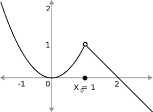
For the sake of robustness, the shape functions sometimes have a slope discontinuity from one element to the next. (Figure 3‑2) That is the source of stress singularities. Stress depends on the slope of the shape function. And if the slope is completely different at either side of the node, what value should you take right at the node?
Software developers created some very good answers to that question. In 99% of all cases, they smooth over the discontinuity and provide reliable answers. But for a few locations, the smoothing math doesn’t work. In those cases, the calculations involve dividing by the distance between the centers of the two adjacent elements. As the elements get smaller, the distance between centers also grows smaller. The smaller distance exaggerates the slope discontinuity. If the elements were to get infinitely small, you have zero distance between element centers. That really exaggerates the discontinuity, resulting in infinite stress. Annoying, but predictable from the theory. Stripped down to essentials, stress singularities are just a quirk of FEA mathematics that work very well in every other case.

An important feature to understand about the finite element method is that it allows local inaccuracies, since it is formulated in a way that minimizes the global error in the model.
-Walter Frei [4]
It feels disconcerting to state that FEA has known points of error, but we somehow still trust it. In truth, you should never blindly trust FEA. Neither will the engineer running the analysis. Neither did the software developers who created the FEA. They ran something called a patch test, which is a numerical test to ensure these local discontinuities do not alter the global solution that the computer calculated. [5] The developers ensured that these small errors don’t affect the overall physics of your structure.
Here is the crux of the problem: FEA singularities occur at intersections of plate or other sharp changes in geometry, like a right-angle corner. They appear as excessive stress concentrations. Problem is that stress concentrations naturally happen in those same spots. Is that spike in stresses a singularity, or something of genuine concern?
The best way to detect a singularity is to study how it behaves with successive mesh refinements. [4] A stress singularity should be concentrated to one cell near the corners of plate elements. Get a report of the stresses for those few cells and plot how the stress varies against cell size at the corner. For a stress singularity, the stress will continue to rise without convergence as you refine the mesh in the corner. The key aspect is no convergence. Figure 4‑1 shows an example of this. The stress never tapers off to some finite value. As the element size moves down to zero, the slope of the plot gets steeper. At this rate, it will curve right up to infinity. If it never converges, you have a stress singularity, and you can ignore it.
Of course, on a big ship assembly, this requires a lot of effort to check every stress concentration. Here is a trick to filter your results and identify the true tough cases. Create a graphic plot showing the strain energy. (Figure 4‑1) As you refine the mesh, compare the changes in your strain energy graph to the stress graph.
The strain energy graph should change far less than the stress graph. This is due to the different math involved in the two quantities. Strain energy requires numerical integration of the core FEA solution data. The integration process minimizes the errors of a stress singularity. Comparing the stress plots and strain energy plots quickly identifies obvious singularities and lets you focus on the truly questionable cases.
But what about the grey areas? What if you are not sure? FIND OUT! If it is not a stress singularity, then sharp rises in the stress may spark failure in your structure. Try adding a small fillet or other small change to the geometry and see if that radically alters the stress patterns. Or try further mesh refinement. And if you are a client reviewing an FEA report, make sure the engineer sufficiently proved that all questionable stress concentrations were singularities.


Don’t trust the FEA, but do trust your engineer. They are trained to recognize stress singularities and run tests to detect them, just like a doctor eliminating cancer. Once properly identified, the engineer has several tools to handle singularities. This is part of the quality assurance that engineers perform to make FEA reliable. Under proper supervision, these few bad spots will not discredit the rest of your simulation.
| [1] | H. Sonnerlind, “Singularities in Finite Element Models: Dealing with Red Spots,” COMSOL, 3 Jun 2015. . Available: https://www.comsol.com/blogs/singularities-in-finite-element-models-dealing-with-red-spots/. . |
| [2] | S. Adeeb, “Introduction to Solid Mechanics & Finite Element Analysis.,” University of Alberta, 2017. . Available: https://sameradeeb.srv.ualberta.ca. . |
| [3] | SilverStar, “Removable Discontuity,” Wikipedia, 3 Dec 2006. . Available: https://en.wikipedia.org/wiki/File:Removable-discontinuity.svg. . |
| [4] | W. Frei, “How to Identify and Resolve Singularities in the Model When Meshing,” COMSOL, 29 Oct 2013. . Available: https://www.comsol.com/blogs/how-identify-resolve-singularities-model-meshing/. . |
| [5] | O. C. Zienkiewicz, R. L. Taylor and J. Z. Zhu, The Finite Element Method: Its Basis and Fundamentals, Sixth Edition, Burlington, MA: Elsevier Butterworth-Heinemann, 2005. |
| [6] | CAD Familiy.com, “ANSYS Mechanical-Buckling Analysis,” CAD Family.com, 30 Mar 2016. . Available: https://www.cadfamily.com/a/CAE_FEA_CFD/ANSYS/ANSYS-Mechanical-Buckling-Analysis_11879.html. . |
| [7] | O. C. Zienkiewicz and R. L. Taylor, The Finite Element Method for Solid and Structural Mechanics, Sixth Edition, Burlington, MA, USA: Elsevier Butterworth-Heinemann, 2005. |
 https://dmsonline.us/wp-content/uploads/2023/12/HabbakukCover-Small-1.jpg
489
500
Nate Riggins
/wp-content/uploads/2025/06/DMS-logo.svg
Nate Riggins2024-09-24 09:18:002026-04-03 10:11:31Project Habbakuk: A Ship from Ice!
https://dmsonline.us/wp-content/uploads/2023/12/HabbakukCover-Small-1.jpg
489
500
Nate Riggins
/wp-content/uploads/2025/06/DMS-logo.svg
Nate Riggins2024-09-24 09:18:002026-04-03 10:11:31Project Habbakuk: A Ship from Ice! https://dmsonline.us/wp-content/uploads/2023/12/Icebreaker_SpoonBow.webp
217
598
Nate Riggins
/wp-content/uploads/2025/06/DMS-logo.svg
Nate Riggins2024-07-16 09:00:002026-04-03 10:11:31Strong as Ice: Icebreaker Structure
https://dmsonline.us/wp-content/uploads/2023/12/Icebreaker_SpoonBow.webp
217
598
Nate Riggins
/wp-content/uploads/2025/06/DMS-logo.svg
Nate Riggins2024-07-16 09:00:002026-04-03 10:11:31Strong as Ice: Icebreaker Structure https://dmsonline.us/wp-content/uploads/2023/12/USCGC_Healy_WAGB-20_north_of_Alaska-scaled-1.jpg
633
1200
Nate Riggins
/wp-content/uploads/2025/06/DMS-logo.svg
Nate Riggins2024-05-14 09:00:002026-04-03 10:11:31Surviving the Arctic: Polar Class Icebreakers
https://dmsonline.us/wp-content/uploads/2023/12/USCGC_Healy_WAGB-20_north_of_Alaska-scaled-1.jpg
633
1200
Nate Riggins
/wp-content/uploads/2025/06/DMS-logo.svg
Nate Riggins2024-05-14 09:00:002026-04-03 10:11:31Surviving the Arctic: Polar Class Icebreakers https://dmsonline.us/wp-content/uploads/2023/12/MackinawIce1-scaled-1.jpg
883
1200
Nate Riggins
/wp-content/uploads/2025/06/DMS-logo.svg
Nate Riggins2024-03-19 09:00:002026-04-03 10:11:32Ramming the Ice: Icebreaker Propulsion
https://dmsonline.us/wp-content/uploads/2023/12/MackinawIce1-scaled-1.jpg
883
1200
Nate Riggins
/wp-content/uploads/2025/06/DMS-logo.svg
Nate Riggins2024-03-19 09:00:002026-04-03 10:11:32Ramming the Ice: Icebreaker Propulsion https://dmsonline.us/wp-content/uploads/2023/12/MackinawIce2-scaled-1.jpg
1200
985
Nate Riggins
/wp-content/uploads/2025/06/DMS-logo.svg
Nate Riggins2024-01-16 09:00:002026-04-03 10:11:32Breaking the Ice: Icebreakers
https://dmsonline.us/wp-content/uploads/2023/12/MackinawIce2-scaled-1.jpg
1200
985
Nate Riggins
/wp-content/uploads/2025/06/DMS-logo.svg
Nate Riggins2024-01-16 09:00:002026-04-03 10:11:32Breaking the Ice: Icebreakers https://dmsonline.us/wp-content/uploads/2022/06/MVAltairGeneralArrangementPlan_SmallResolution.webp
299
640
Nate Riggins
/wp-content/uploads/2025/06/DMS-logo.svg
Nate Riggins2022-09-12 06:00:002025-09-30 07:31:20How to Design a Ship
https://dmsonline.us/wp-content/uploads/2022/06/MVAltairGeneralArrangementPlan_SmallResolution.webp
299
640
Nate Riggins
/wp-content/uploads/2025/06/DMS-logo.svg
Nate Riggins2022-09-12 06:00:002025-09-30 07:31:20How to Design a Ship https://dmsonline.us/wp-content/uploads/2020/12/Composite_3d.png
600
800
Nate Riggins
/wp-content/uploads/2025/06/DMS-logo.svg
Nate Riggins2021-01-04 07:00:002026-04-03 10:11:34Composite Materials
https://dmsonline.us/wp-content/uploads/2020/12/Composite_3d.png
600
800
Nate Riggins
/wp-content/uploads/2025/06/DMS-logo.svg
Nate Riggins2021-01-04 07:00:002026-04-03 10:11:34Composite Materials https://dmsonline.us/wp-content/uploads/2018/11/M18016_FeatureImage.jpg
720
1280
Nate Riggins
/wp-content/uploads/2025/06/DMS-logo.svg
Nate Riggins2019-03-18 08:30:532026-04-03 10:11:46Six Ways to Break the Ship
https://dmsonline.us/wp-content/uploads/2018/11/M18016_FeatureImage.jpg
720
1280
Nate Riggins
/wp-content/uploads/2025/06/DMS-logo.svg
Nate Riggins2019-03-18 08:30:532026-04-03 10:11:46Six Ways to Break the Ship https://dmsonline.us/wp-content/uploads/2018/11/M18013_FeatureImage.jpg
720
1280
Nate Riggins
/wp-content/uploads/2025/06/DMS-logo.svg
Nate Riggins2019-02-18 08:30:162026-04-03 10:11:47Improve Engineering Value
https://dmsonline.us/wp-content/uploads/2018/11/M18013_FeatureImage.jpg
720
1280
Nate Riggins
/wp-content/uploads/2025/06/DMS-logo.svg
Nate Riggins2019-02-18 08:30:162026-04-03 10:11:47Improve Engineering Value